
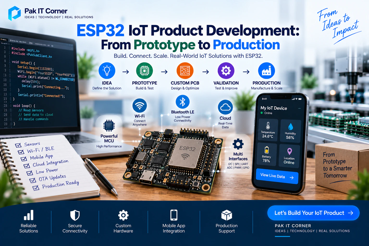
ESP32 has become one of the most popular platforms for developing connected products. It combines powerful processing, Wi-Fi, Bluetooth, flexible interfaces, low-power capabilities, and a large development ecosystem in a compact and affordable platform.
Building a working ESP32 prototype, however, is only the beginning.
A product that works on a development board on your desk is very different from a reliable device that can be manufactured, deployed, updated, and supported in the real world.
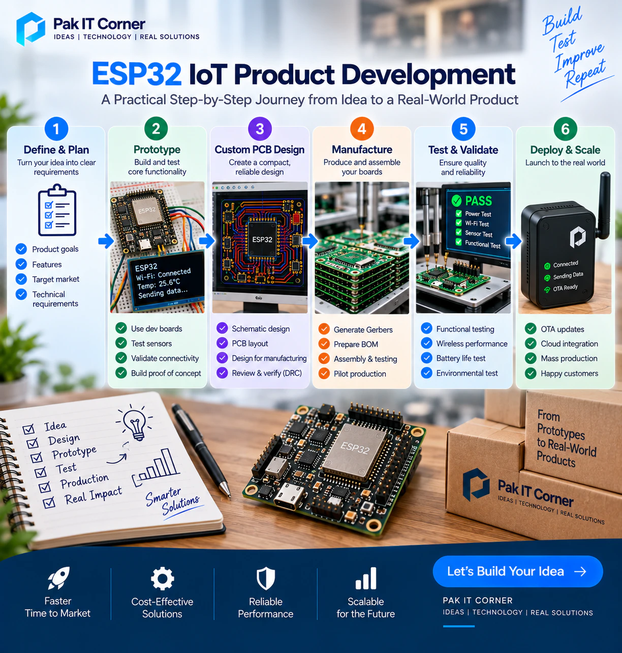
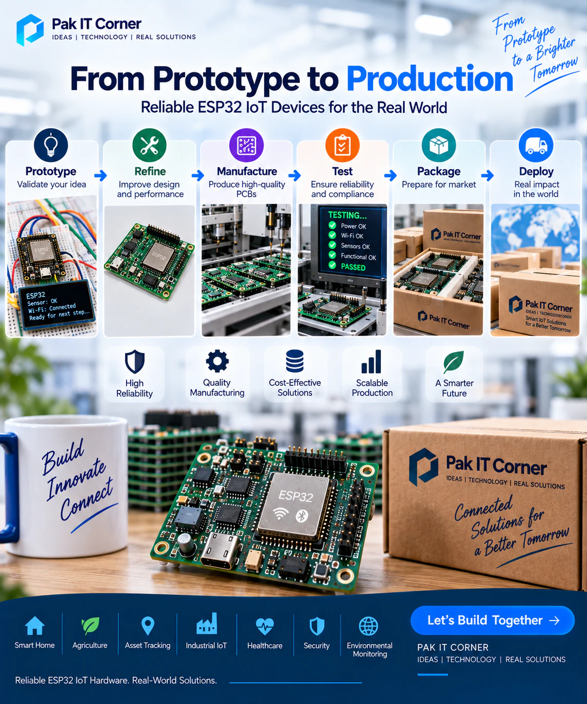
Moving from prototype to production requires careful decisions about hardware, firmware, connectivity, power management, PCB design, security, testing, manufacturing, and long-term maintenance.
This guide explains the complete ESP32 IoT product development process — from the first prototype to a production-ready connected device.
What Is an ESP32 IoT Product?
An ESP32 IoT product is a connected electronic device built around an ESP32 microcontroller or module.
Depending on the application, the device may collect sensor data, control equipment, communicate with a companion mobile application, send information to a cloud platform, or perform several of these functions simultaneously.
Typical ESP32 IoT products include:
- Smart home devices
- Environmental monitoring systems
- GPS tracking devices
- Agricultural monitoring systems
- Industrial controllers
- Security devices
- Smart access-control systems
- Battery-powered sensors
- Remote monitoring equipment
- Connected appliances
- Wearable devices
- Asset tracking systems
The ESP32 often acts as the central controller connecting sensors, actuators, wireless communication, firmware, and the application or cloud platform.
Why ESP32 Is Popular for IoT Development
ESP32 provides many features required by modern connected products in a single platform.
Depending on the ESP32 variant, these may include:
- Wi-Fi (802.11 b/g/n)
- Bluetooth Low Energy (BLE)
- GPIO (General Purpose Input/Output)
- ADC (Analog-to-Digital Converter)
- PWM (Pulse Width Modulation)
- UART
- I2C
- SPI
- USB
- Low-power operating modes (Deep Sleep, Light Sleep)
- Hardware security features (Secure Boot, Flash Encryption, Cryptographic Accelerators)
- OTA firmware update support
This makes it possible to build sophisticated IoT devices without requiring a large number of additional components.
ESP32 also has a mature software ecosystem and is supported by development environments such as ESP-IDF, Arduino, and PlatformIO.
Prototype vs Production Product
One of the biggest mistakes in IoT development is treating a working prototype as a finished product.
A prototype is primarily designed to prove that an idea works.
A production device must work reliably under real-world conditions and be practical to manufacture repeatedly.
A prototype may use:
- ESP32 development boards
- Breadboards
- Jumper wires
- External sensor modules
- USB power
- Temporary firmware
- Hardcoded Wi-Fi credentials
A production product usually requires:
- A custom PCB (see our complete PCB design guide)
- Stable power architecture
- Production-grade connectors
- Reliable firmware
- Secure device provisioning
- Enclosure integration
- OTA updates
- Manufacturing test procedures
- Device identification
- Production documentation
The transition between these two stages is where much of the real engineering work happens.
Step 1: Define the Product Requirements
Before designing hardware or writing large amounts of firmware, clearly define what the device must do.
Important questions include:
- What problem does the product solve?
- What sensors are required?
- What outputs or actuators must be controlled?
- Will it use Wi-Fi, BLE, LoRa, cellular, or multiple technologies?
- Does it require a mobile application?
- Does it require cloud connectivity?
- Will it operate from a battery?
- How long should the battery last?
- Will it operate indoors or outdoors?
- What temperature and environmental conditions must it tolerate?
- Does it require remote firmware updates?
- How many devices may eventually be manufactured?
These requirements influence nearly every engineering decision that follows.
Step 2: Choose the Correct ESP32 Variant
ESP32 is a family of microcontrollers rather than a single device.
Different variants provide different processing capabilities, interfaces, wireless features, memory options, and power characteristics.
Common families include:
- ESP32 (Original): Dual-core Xtensa, Wi-Fi 4, Bluetooth 4.2 / BLE, versatile GPIO.
- ESP32-S2: Single-core Xtensa, native USB OTG, Wi-Fi 4, cost-effective for USB and display products.
- ESP32-S3: Dual-core Xtensa with vector instructions for AI/ML, Wi-Fi 4, BLE 5, native USB, rich GPIO.
- ESP32-C3: Single-core 32-bit RISC-V, Wi-Fi 4, BLE 5, pin-compatible with ESP8266, highly cost-efficient.
- ESP32-C6: Single-core 32-bit RISC-V, Wi-Fi 6 (2.4 GHz), BLE 5, 802.15.4 (Zigbee & Thread / Matter support).
For example, an ESP32-S3 can be a strong option for products requiring Wi-Fi, BLE, USB functionality, additional processing capability, or more advanced applications.
The best ESP32 variant should be selected according to the actual requirements rather than simply choosing the newest device.
Consider:
- Required GPIO count
- Flash and RAM requirements
- Wi-Fi requirements
- Bluetooth requirements
- USB requirements
- Processing requirements
- Power consumption
- Package or module availability
- Long-term component availability
Step 3: Create the System Architecture
Before building the device, create a clear system-level architecture.
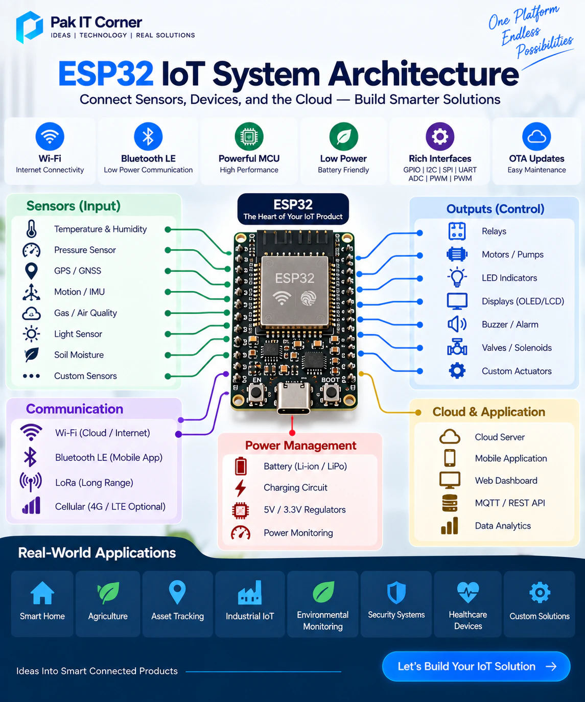
A typical ESP32 IoT architecture might look like:
Sensors → ESP32 → Wi-Fi/BLE → Mobile App or Cloud
A more advanced device might use:
Sensors → ESP32 → Wi-Fi → Cloud Server → Mobile App
Other products may include:
ESP32 → LoRa → Gateway → Internet → Cloud
The architecture should identify every major subsystem, including:
- Microcontroller
- Sensors
- Power supply
- Battery
- Charging circuit
- Communication interfaces
- External memory
- Actuators
- User interface
- Mobile application
- Backend
- Cloud services
This helps prevent major architectural changes later.
Step 4: Build a Functional Prototype
The first prototype should focus on validating the core functionality.
Development boards and sensor modules are extremely useful at this stage.
For example, an early prototype may contain:
- ESP32 development board
- Temperature sensor
- GPS module
- LoRa module
- OLED display
- Battery
- Mobile application
The objective is not to make the prototype beautiful.
The objective is to answer important technical questions:
- Can the sensors communicate correctly?
- Is wireless range sufficient?
- Can the application connect reliably?
- Is the selected battery appropriate?
- Does the device perform the required function?
Solve these questions before investing heavily in custom hardware.
Step 5: Design the Firmware Architecture
Firmware should be structured for future development rather than becoming one large program.
A production-oriented firmware architecture may separate:
- Hardware drivers
- Sensor management
- Communication
- Device configuration
- Application logic
- Data storage
- Error handling
- OTA updates
- Diagnostics
Separating these responsibilities makes firmware easier to test and maintain.
It also reduces the risk that changing one feature breaks unrelated parts of the system.
Step 6: Define the Communication Protocol
The communication protocol between the ESP32 and other parts of the system should be defined early.
For example, the device may exchange:
- Device ID
- Sensor readings
- Battery percentage
- Connection status
- Firmware version
- Commands
- Configuration parameters
- Error codes
A predictable protocol makes integration between firmware, mobile applications, gateways, and cloud services significantly easier.
Step 7: Choose Between BLE and Wi-Fi
Many ESP32 products use Bluetooth Low Energy, Wi-Fi, or both (see our complete BLE vs Wi-Fi IoT guide).
Bluetooth Low Energy
BLE is useful for:
- Initial device setup
- Local control
- Battery-powered devices
- Device configuration
- Short-range communication
- Operation without internet access
Wi-Fi
Wi-Fi is useful for:
- Cloud communication
- Remote monitoring
- Larger data transfers
- OTA firmware updates
- Internet-connected devices
- Real-time dashboards
Many commercial IoT products combine both technologies.
For example:
BLE → Initial setup and Wi-Fi provisioning
Wi-Fi → Normal cloud communication
This can provide a better user experience than requiring the user to manually configure the device.
Step 8: Design Reliable Wi-Fi Provisioning
One important challenge is how a new product receives the customer's Wi-Fi credentials.
Hardcoding a network name and password is not appropriate for a commercial product.
Common provisioning approaches include:
- BLE Provisioning: Mobile app connects directly to ESP32 over BLE and sends Wi-Fi SSID and password securely.
- SoftAP (Access Point) Mode: ESP32 broadcasts its own temporary Wi-Fi network with a captive configuration portal.
- QR Code Assisted Onboarding: Pairing device metadata encoded in a QR code scanned by the mobile app.
- Espressif Unified Provisioning (ESP-IDF Protocomm): Industry-standard secure encrypted handshake over BLE or Wi-Fi.
The user should be able to install the device without technical knowledge.
Provisioning should also allow the network credentials to be changed later.
Step 9: Move From Development Board to Custom PCB
Once the functional prototype has been validated, the next stage is usually a custom PCB.
A custom PCB can:
- Reduce product size dramatically
- Eliminate loose wires and breadboard unreliability
- Improve electrical and RF stability
- Lower production cost at scale
- Improve power efficiency and thermal dissipation
- Integrate onboard sensors and connectors
- Fit precisely into custom injection-molded or 3D-printed enclosures
- Simplify automated surface mount assembly (SMT)
The PCB should be designed around the actual product requirements rather than simply copying a development board.
Step 10: ESP32 Module vs Bare Chip
Production designs can use an ESP32 module or the ESP32 chip directly.
For many products, a certified ESP32 module is an attractive option because it simplifies RF design.
Modules commonly integrate:
- ESP32 microcontroller chip
- Flash memory (and PSRAM where applicable)
- Crystals (main oscillator and 32.768 kHz RTC)
- RF matching components and filters
- Onboard PCB trace antenna or U.FL / IPEX external antenna connector
- Pre-certified RF shield (FCC, CE, IC, TELEC, SRRC, RoHS)
A bare-chip design can provide greater control over size and cost at high production volumes, but it requires significantly more RF and PCB design expertise, specialized impedance matching, and expensive regulatory testing.
For many startups and moderate-volume products, an ESP32 module (such as ESP32-WROOM, ESP32-WROVER, or ESP32-S3-WROOM) is the more practical choice.
Step 11: Design a Reliable Power Supply
Power design is one of the most important parts of an ESP32 product.
Wireless transmission can create short current peaks (reaching 400 mA to 500 mA during RF bursts). A poorly designed supply may cause:
- Random resets and brownouts
- Wi-Fi connection instability
- BLE disconnections
- Sensor measurement errors
- Boot and flash failures
The power architecture should provide sufficient current under worst-case operating conditions.
Good design practices include:
- Correct low-dropout regulator (LDO) or buck converter selection (minimum 800 mA – 1A rating recommended)
- Proper ceramic decoupling capacitors (100nF, 1uF, 10uF) close to VDD pins
- Short, wide power traces with solid ground return paths
- Adequate bulk capacitance (22uF – 100uF tantalum or low-ESR ceramic) near the module
- Proper thermal relief and ground copper pours
Power design should be tested during actual wireless activity, not only while the device is idle.
Step 12: Battery-Powered ESP32 Products
Battery-powered IoT products require additional planning.
The system may need:
- Dedicated Li-ion / LiPo battery charger IC (e.g. TP4056 or MCP73831)
- Battery protection circuit (over-charge, over-discharge, short-circuit)
- Ultra-low quiescent current (Iq) voltage regulation
- Battery voltage measurement (high-impedance resistive divider with enable switch)
- USB-C charging port with ESD protection
- Low-power firmware architecture leveraging Deep Sleep
- Wakeup triggers via RTC timer, GPIO interrupts, or external sensor thresholds
Battery life should be calculated based on realistic operating behavior:
Battery life ≈ Battery capacity ÷ Average current consumption
Average consumption must include:
- Active processing current
- Wi-Fi transmission bursts
- BLE advertising and connection states
- Sensors and peripherals
- Displays (if present)
- GNSS/GPS current draw
- Deep sleep quiescent current (< 20µA target)
- Regulator and quiescent losses
Real-world testing with power profiling equipment should always confirm theoretical estimates.
Step 13: Integrate Sensors Correctly
ESP32 can communicate with sensors through interfaces such as:
- I2C: Temperature, humidity, barometric pressure, IMU/accelerometers, ambient light, air quality.
- SPI: High-speed displays, external flash, SD cards, RF transceivers.
- UART: GNSS/GPS modules, cellular modems, industrial sensors (RS485/Modbus).
- ADC: Analog soil moisture, battery voltage sensing, analog transducers.
- GPIO: Digital interrupts, pulse counters, optical switches, relay triggers.
Sensor selection should consider more than basic functionality:
- Measurement accuracy and resolution
- Operating voltage compatibility (3.3V vs 5V level shifting)
- Current consumption in active and sleep modes
- Operating temperature range
- Factory calibration and drift
- Interface protocol and pull-up resistor values
- Component availability and multi-sourcing
- BOM cost
For precision measurements, PCB layout and power quality can significantly affect sensor performance.
Step 14: Add GNSS When Location Is Required
Tracking products may use GNSS modules (GPS, GLONASS, Galileo, BeiDou) for positioning.
Typical information includes:
- Latitude and longitude
- Ground speed and heading
- Precise UTC timestamp
- Satellite fix status and Dilution of Precision (DOP)
GNSS design requires attention to:
- Active vs passive antenna selection
- Antenna ground plane dimension and placement
- RF isolation from high-speed clocks and ESP32 Wi-Fi emissions
- Power management (power gating GNSS module when fix is not needed)
- Cold-start time (TTFF — Time to First Fix)
- Enclosure RF transparency (avoid metal shielding above antenna)
- UART communication baud rates and buffer management
The GNSS antenna should not simply be placed wherever there is unused PCB space.
Step 15: Add LoRa for Long-Range Communication
Some ESP32 products need communication over distances where BLE or Wi-Fi is unsuitable.
LoRa (Long Range) is particularly useful for:
- Agricultural monitoring (smart irrigation, soil probes across acreage)
- Remote environmental stations
- Asset tracking across logistics yards
- Industrial campus monitoring
- Infrastructure and utility metering
A typical hybrid architecture may use:
Sensor Node (ESP32 + LoRa) → LoRa Gateway → Internet → Cloud Dashboard
The ESP32 manages sensor acquisition and local logic while the LoRa radio (such as SX1262 or SX1276) provides long-range, low-power telemetry over several kilometers.
Step 16: Control Motors, Pumps, Relays, and Other Loads
ESP32 GPIO pins should never directly power high-current loads.
Products controlling motors, pumps, solenoids, or relays typically require additional driver circuitry.
Depending on the load, this may include:
- Logic-level N-channel MOSFETs for DC load switching
- Dedicated gate driver ICs for high-side switching
- Flyback diodes across inductive coils (relays, motors, solenoids) to suppress back-EMF spikes
- Optocouplers for galvanic isolation between microcontroller logic and high-voltage AC circuits
- Solid-state relays (SSRs) or electromechanical relays with snubbers
- Motor driver H-bridge ICs (e.g. DRV8833, TB6612, or DRV8871)
The PCB layout should strictly separate noisy, high-current power paths from sensitive analog, digital, and RF sections.
Step 17: Develop the Mobile Application
For many IoT products, the mobile application is a major part of the user experience.
The application may allow users to:
- Add new devices to their account
- Configure Wi-Fi and network credentials over BLE
- View real-time sensor dashboards and historic graphs
- Control outputs, relays, switches, and parameters
- Check battery status and charging indicators
- Receive push notifications and threshold alerts
- View device connection logs and diagnostic history
- Manage multi-user access and permissions
- Trigger remote OTA firmware updates
The hardware and mobile application should therefore be designed together rather than as completely separate projects.
Step 18: Choose Native or Cross-Platform Development
The mobile application may be developed using native technologies such as Swift (iOS) and Kotlin (Android) or cross-platform frameworks such as Flutter.
Flutter can be useful when a business wants Android and iOS applications from a shared codebase, reducing development time and cost while delivering smooth 60/120 FPS performance.
Native development may be preferred when the application requires deep, specialized platform-specific behavior or continuous background peripheral synchronization.
The correct choice depends on:
- Required features and device hardware access
- Budget and time-to-market
- BLE scanning and connection requirements across platforms
- Background execution and notification needs
- Platform integrations and ecosystem ties
- Long-term maintenance strategy
Step 19: Design the Backend and Cloud Architecture
Cloud-connected ESP32 products often require backend infrastructure.
The backend may manage:
- User accounts and secure authentication
- Device registration and cryptographic credential validation
- Sensor telemetry ingestion and time-series databases
- Downlink commands and configuration queues
- Alert engines, email triggers, and push notifications
- Device ownership tracking and access rights
- Firmware version registries and OTA binary hosting
- Fleet management and system analytics
Communication may use technologies such as REST APIs, MQTT, and WebSockets.
The cloud architecture should be designed according to the expected device count and data volume to prevent high operating costs as the product scales.
Step 20: Use MQTT Where Appropriate
MQTT is widely used in IoT systems because it provides lightweight, efficient publish/subscribe messaging over TCP/IP.
For example:
Device publishes telemetry:
devices/device123/temperature
Application or backend sends commands:
devices/device123/commands
MQTT can be particularly useful for real-time telemetry and remote control because of its minimal packet overhead and Quality of Service (QoS) levels.
However, TLS encryption (MQTTS), mutual authentication, keep-alive timers, exponential-backoff reconnect behavior, and message delivery guarantees must be designed carefully.
Step 21: Give Every Device a Unique Identity
Production devices should have unique identities.
A device identity may include:
- Unique hardware serial number
- Factory-programmed device ID
- Factory MAC address
- QR code printed on PCB, enclosure, and packaging
- Cryptographic device private key or certificate
This identity can be used for:
- Customer device registration
- Account ownership linking
- Mutual TLS authentication to the cloud broker
- Traceable manufacturing batch records
- Technical customer support and RMA tracking
- Targeted firmware update distribution
Unique identity becomes increasingly important as the number of deployed devices grows.
Step 22: Plan Device Ownership and Provisioning
A commercial IoT platform needs to know which user owns which device.
A typical process might be:
Manufacturing → Unique device created → Customer scans QR code → Device registered → Device linked to account
The system should also define what happens when:
- A device is sold or transferred to another user
- Ownership is reassigned within a company
- The device is factory reset via physical button
- Wi-Fi credentials are changed or lost
- A hardware unit is replaced under warranty
These workflows are far easier to design before thousands of devices are deployed in the field.
Step 23: Secure the Product
IoT security should never be treated as an optional feature or an afterthought.
Important security measures include:
- Encrypted Transport: Enforce TLS 1.2/1.3 for all HTTP and MQTT traffic.
- Unique Credentials: Avoid hardcoded shared passwords; assign unique client certificates or tokens per device.
- ESP32 Secure Boot: Prevents unauthorized, tampered firmware from executing on the microcontroller.
- ESP32 Flash Encryption: Protects firmware, credentials, and configuration keys stored in external flash memory.
- Signed Firmware Images: Ensures that OTA updates are accepted only if signed by the developer's private key.
- Protected Cloud APIs: Implement token expiration, scoped permissions, and role-based access control.
- Disable Debug Interfaces: Blow JTAG and UART download mode security fuses before shipping mass-production hardware.
Avoid using the same permanent secret across every manufactured device. If one device is compromised, shared credentials can expose the entire fleet.
Step 24: Implement OTA Firmware Updates
Once devices are deployed in customers' hands, physically accessing every unit for firmware updates is practically impossible.
Over-The-Air (OTA) updates allow firmware to be updated remotely over Wi-Fi or cellular connections.
OTA can be used to:
- Fix bugs discovered in the field
- Improve wireless connection reliability
- Add new features and capabilities
- Patch security vulnerabilities
- Improve power efficiency and battery life
OTA must therefore be considered during initial architecture planning rather than added as a last-minute patch.
Step 25: Make OTA Updates Safe
An interrupted firmware update must never "brick" or permanently disable the product.
A robust OTA strategy incorporates:
- Dual-Partition Scheme (A/B partitioning): Firmware is written to an inactive partition while the active partition continues running.
- Rollback Mechanism: If the new firmware fails to boot or cannot establish cloud contact, the bootloader automatically reverts to the previous working partition.
- Cryptographic Signature Validation: The bootloader verifies the image hash and digital signature before swapping partitions.
- Version Checking: Prevents accidental downgrades to vulnerable or incompatible firmware releases.
- Power-Loss Protection: Resilient flash writing that survives sudden battery or power disconnection during download.
The product must always recover safely under any unexpected update interruption.
Step 26: Handle Network Failures
Real-world networks are inherently unreliable.
Wi-Fi disappears. Routers reboot. Internet service providers experience outages. Cloud servers undergo maintenance.
The firmware must handle these conditions gracefully.
A reliable product should:
- Detect disconnections immediately without hanging the main loop
- Implement exponential backoff retry algorithms to avoid flood congestion
- Avoid infinite blocking network calls
- Cache critical sensor data in local memory (SPIFFS, LittleFS, or NVS) until reconnection
- Reconnect automatically when the network returns
- Continue local functionality, display updates, and safety controls offline
Testing firmware only in ideal lab Wi-Fi conditions hides serious real-world failure modes.
Step 27: Use Watchdogs and Recovery Mechanisms
Long-running embedded products must be capable of autonomous recovery from unexpected software hangs.
Hardware watchdog timers (WDT) will restart the microcontroller if the firmware task fails to reset the watchdog within a defined timeout.
However, watchdogs are not a substitute for fixing underlying firmware bugs.
They should be part of a broader reliability architecture that includes:
- Task-level FreeRTOS watchdog monitoring
- Defensive input validation on all communication channels
- Controlled timeout handling for all peripherals (I2C/SPI)
- Crash logging and core-dump capture stored in flash for post-mortem analysis
- Self-healing reconnection state machines
Step 28: Manage Local Data Storage Carefully
Some devices need to temporarily or permanently store:
- Configuration parameters and user preferences
- Calibration offsets and sensor lookup tables
- Wi-Fi credentials and network history
- Device state and error counters
- Unsynchronized sensor telemetry during network drops
ESP32 provides Non-Volatile Storage (NVS), LittleFS, and SPIFFS file systems in flash.
Flash memory cells have a finite write endurance (typically 10,000 to 100,000 cycles). Avoid writing to flash on every sensor reading. Cache data in RAM and write to flash only when values change or during controlled shutdown cycles.
Step 29: Design the Enclosure Around the Electronics
Mechanical design and electronics design should happen concurrently.
The enclosure directly impacts:
- PCB dimensions and mounting hole positions
- Connector accessibility (USB-C, power jack, external sensors)
- Antenna performance and RF transparency
- Physical button locations and tactile feel
- LED light-pipe visibility
- Sensor exposure to airflow and ambient environment
- Thermal dissipation from power regulators and MCU
- Waterproofing gaskets and IP ingress protection ratings
Waiting until the PCB layout is finished before designing the enclosure frequently creates costly PCB re-spins.
Step 30: Protect Wireless Antenna Performance
ESP32 Wi-Fi and BLE performance can be severely degraded by poor mechanical or PCB layout.
Key guidelines include:
- Follow module manufacturer keep-out zones strictly — do not place copper planes, traces, or components under or directly around the PCB antenna.
- Avoid placing large metal objects, batteries, displays, or screws adjacent to the antenna.
- Ensure the enclosure material is RF-transparent (e.g. ABS, polycarbonate) and maintain clearance between the antenna and the enclosure wall.
- If using an external antenna via IPEX/U.FL, route the RF coaxial cable away from high-speed switching signals.
- Perform RF range and packet loss tests with the device fully assembled inside its final enclosure.
Step 31: Build the First Custom PCB Prototype
Do not immediately manufacture hundreds of boards after finishing the PCB layout.
Start with a small prototype batch (typically 5 to 10 units).
The first custom PCB prototype verifies:
- Power supply rails and regulator output voltages
- ESP32 boot, reset, and strapping pin behavior
- USB-to-UART communication and firmware programming
- All I2C, SPI, and UART sensor interfaces
- Wi-Fi and BLE RF signal strength and connection range
- Battery charging, fuel gauge measurement, and power path switching
- Output drive capabilities (MOSFETs, relays, LEDs)
- Mechanical fit inside the prototype enclosure
- Total current consumption in active and deep sleep states
Problems identified at this stage are far cheaper and faster to fix than errors discovered during volume production.
Step 32: Use Controlled First Power-Up
The first power-up of a newly assembled PCB must be carefully controlled.
Before applying full operating power:
- Inspect the board under a microscope for solder bridges, tombstoned components, and misaligned pins.
- Measure resistance between power rails (3.3V, 5V, VBUS) and ground to verify there are no dead shorts.
- Check polarized component orientations (diodes, electrolytic capacitors, IC pin 1 indicators).
- Power the board from a current-limited benchtop power supply set to 50 – 100 mA limit.
- Verify regulator output voltages with a multimeter before letting the ESP32 run.
A current-limited bench supply prevents immediate component destruction if a short circuit or assembly error is present.
Step 33: Test Every Hardware Subsystem
Bring up the board systematically rather than testing everything all at once.
A practical order of verification is:
- Input power and protection circuitry
- Voltage regulators (3.3V output rail)
- ESP32 programming interface (USB/UART and strapping pins)
- Status LEDs and basic GPIO toggling
- I2C bus scanning and sensor responses
- SPI communication to displays or external memory
- Sensors: reading realistic environmental values
- Wireless radios: Wi-Fi scanning and BLE advertising
- Battery charger IC operation and charge termination
- Outputs, drivers, relays, and actuators
Testing one subsystem at a time makes hardware faults and solder issues straightforward to isolate.
Step 34: Create Hardware Test Firmware
Production development benefits greatly from dedicated test firmware.
Instead of testing through the complex application code, lightweight test firmware verifies each component individually:
- Blinks status LEDs in sequence
- Reads button presses and logs state changes
- Polls all connected sensors and prints measurements over UART
- Measures ADC battery voltage and charging status
- Cycles motor drivers or relays with controlled pulses
- Scans for Wi-Fi access points and measures RSSI
- Advertises over BLE and accepts a test connection
- Pings LoRa transceivers or reads GNSS NMEA sentences
This test firmware becomes invaluable for engineering validation and factory testing on the assembly line.
Step 35: Test Wireless Performance
Wireless performance should be measured systematically rather than assumed.
Verify:
- BLE advertising range and connection stability across distances
- Wi-Fi RSSI at varying distances from the access point
- Connection throughput and packet loss rates
- Performance through drywall, concrete, and commercial obstacles
- Wireless performance when the device is enclosed in its plastic housing
- Electromagnetic interference (EMI) from DC-DC switching regulators or high-speed traces affecting RF reception
If the product uses LoRa, conduct field tests at target operational distances with realistic antenna orientations.
Step 36: Measure Real Battery Performance
Battery performance must be verified with real hardware in real operating conditions.
Measure current draw during:
- Power-on boot sequence
- Idle running state
- Wi-Fi connection handshake and DHCP negotiation
- Wi-Fi transmission bursts (MQTT publish)
- BLE advertising intervals and active connection
- Sensor data acquisition cycles
- Deep Sleep state (confirming target microamp consumption)
These empirical measurements frequently expose unexpected power drains that theoretical spreadsheets overlook — such as unconfigured floating GPIOs, active pull-up resistors, or leaky sensor modules.
Step 37: Test Failure Conditions
A truly reliable product is engineered for failure conditions, not just ideal operation.
Deliberately test:
- Sudden Wi-Fi signal loss during an active transmission
- Cloud server downtime and unresponsive API endpoints
- Low battery voltage dropouts and graceful shutdown behavior
- Accidental disconnection or failure of an external sensor
- Spontaneous brownouts and rapid power cycling
- Interrupted OTA update during binary download
- User entering invalid Wi-Fi passwords or malformed configuration data
- Over-temperature or sub-zero operating environments
A production-ready device must handle every failure mode predictably and recover without requiring a manual reset from the user.
Step 38: Add Diagnostics
Diagnostic logging saves immense amounts of engineering and support time once devices are deployed.
Valuable diagnostics include:
- Firmware version, build timestamp, and Git commit hash
- Reset reason (Power-on, Watchdog, Brownout, Software restart)
- Wi-Fi RSSI, BSSID, and reconnect event counters
- Battery voltage, charge cycles, and power rail status
- Sensor communication error counts
- System uptime and free heap memory statistics
- Error codes and crash logs stored in flash
Exposing this information through the companion mobile app, a local diagnostic webpage, or a cloud telemetry stream makes resolving customer issues straightforward.
Step 39: Optimize the BOM
Once the prototype operates reliably, conduct a detailed Bill of Materials (BOM) review.
Look for:
- Unnecessarily expensive or over-specified components
- Hard-to-source parts with single-distributor dependencies
- Components with long lead times (26+ weeks)
- Consolidating resistor and capacitor values to reduce unique part count on the pick-and-place feeder
- Components nearing End-of-Life (EOL) status
However, cost reduction should never sacrifice reliability. Saving a few cents on a substandard capacitor or regulator can lead to field failure rates that cost thousands of dollars in warranty replacements.
Step 40: Design for Manufacturing
A PCB that can be hand-soldered in a lab may still be difficult and expensive to assemble in a factory.
Design for Manufacturing (DFM) guidelines include:
- Using standard surface mount package sizes (0603, 0805, SOIC, QFN) where practical
- Maintaining adequate clearance between components for solder paste stencils and pick-and-place nozzles
- Adding optical fiducial markers on PCB corners and high-density ICs for automated machine alignment
- Designing panelization with v-scoring or mouse-bites and break-away rails for automated conveyor transport
- Placing accessible test points (1 mm diameter copper pads) on all power rails, programming pins, and communication lines
- Ensuring all components are placed on a single side of the PCB if possible, avoiding expensive two-pass reflow
Reviewing the design with your assembly partner before fabrication avoids expensive manufacturing revisions.
Step 41: Create a Production Test Procedure
Every manufactured unit must be verified on the factory floor before packaging and shipping.
A typical automated or jig-based production test verifies:
- Power supply voltages under simulated load
- Firmware flashing and secure boot key provisioning
- Wi-Fi and BLE RF signal strength check
- Sensor functionality and value limits
- Output drivers and relay switching
- Battery measurement and charger operation
- Programming of unique serial number and MAC address
- Final firmware version confirmation
A well-designed bed-of-nails test fixture ensures that testing a completed board takes less than 30 seconds.
Step 42: Assign Serial Numbers
Every manufactured product should have an immutable, traceable identity.
Serial numbers should link each physical board to:
- PCB revision and hardware schematic version
- Manufacturing batch and assembly date
- Factory test results and calibration data
- Initial firmware version flashed at the factory
- Assigned cloud device ID and cryptographic public key
Printing this serial number as a scannable QR code on the PCB and enclosure enables complete traceability if field issues occur.
Step 43: Run a Pilot Production Batch
Before committing to thousands of units, manufacture a limited pilot batch (typically 50 to 200 units).
The pilot run tests the complete manufacturing and logistics pipeline:
- PCB fabrication and automated surface-mount assembly yield
- Factory programming and test jig efficiency
- Enclosure fit, snap-fit tolerances, and screw boss strength
- Packaging, labeling, manuals, and accessories
- End-to-end customer onboarding experience and app pairing
Any assembly hiccups, component tolerance issues, or provisioning bugs uncovered during the pilot run can be resolved before scaling up.
Step 44: Prepare Production Documentation
Volume production requires a comprehensive documentation package beyond raw Gerber files.
A production manufacturing package includes:
- RS-274X / Gerber X2 files for all copper, solder mask, silkscreen, and paste layers
- NC drill files with tool assignments and plated/non-plated definitions
- Complete Bill of Materials (BOM) with manufacturer part numbers, descriptions, footprints, and approved alternates
- Pick-and-Place (Centroid) coordinates (X, Y, rotation, board side)
- PCB assembly drawings and silkscreen polarity guides
- Factory programming instructions and flashing binary packages
- Step-by-step Quality Control (QC) and functional test instructions
- Enclosure assembly diagrams, torque specifications, and packaging guidelines
Thorough documentation prevents misunderstandings and guarantees manufacturing consistency across production runs.
Step 45: Manage Hardware Revisions
Hardware inevitably evolves as features are enhanced or obsolete components are replaced.
Implement strict revision tracking:
- Label every PCB with clear revision identifiers (e.g. Rev A, Rev B, Rev C) in the silkscreen and copper.
- Maintain a hardware changelog documenting exact schematic and layout modifications between revisions.
- Incorporate hardware revision detection in firmware (via dedicated resistor divider strapping or board ID pins) so a single firmware binary can adapt to different board iterations.
Careful revision control prevents incompatible firmware updates from being flashed to older field units.
Step 46: Consider Regulatory Requirements
Commercial electronic products must comply with legal regulatory standards in their destination markets.
Common regulatory frameworks include:
- FCC (United States): Part 15 unintentional and intentional radiator rules.
- CE (European Union): Radio Equipment Directive (RED), EMC, and Low Voltage Directive (LVD).
- IC / ISED (Canada): Radio and interference standards.
- RoHS & WEEE: Hazardous substance restrictions and electronic waste recycling compliance.
- UN 38.3: Safety testing standards required for air shipment of lithium batteries.
Using a pre-certified ESP32 module dramatically simplifies and lowers the cost of wireless compliance (enabling modular approval), but the complete product must still pass unintentional radiator emissions testing in its final enclosure.
Step 47: Plan Long-Term Product Support
Shipping product to your first customers is not the finish line — it is the beginning of the product lifecycle.
Plan for multi-year product maintenance:
- Ongoing firmware bug fixes and OTA updates
- Mobile OS compatibility updates for iOS and Android updates
- Cloud infrastructure scalability and database optimization
- Security patching for new cryptographic vulnerabilities
- Component obsolescence management and drop-in replacements
- Customer onboarding support and RMA replacement policies
Thinking about long-term support during the architecture phase ensures a profitable, sustainable connected hardware business.
Prototype vs Production Checklist
Prototype Stage
- Validate core concept and product hypothesis
- Test candidate sensors and verify communication interfaces
- Evaluate ESP32 variant capabilities (memory, GPIO, processing)
- Verify BLE and Wi-Fi connectivity proof-of-concept
- Develop basic functional firmware
- Build initial companion mobile app screen
- Confirm overall system architecture
Engineering Stage
- Design custom schematic and professional PCB layout
- Structure modular production firmware (ESP-IDF or FreeRTOS)
- Implement production mobile app (Flutter / Native iOS & Android)
- Build secure cloud backend and database infrastructure
- Implement security (TLS, secure boot, flash encryption)
- Integrate robust dual-partition A/B OTA updates
- Design 3D mechanical enclosure with thermal and antenna clearance
Validation Stage
- Manufacture and assemble first-article custom PCB prototypes
- Profile actual current consumption across all operating modes
- Perform real-world wireless range and throughput testing
- Stress-test failure conditions, network drops, and power loss
- Validate mechanical fit, connector alignment, and thermal performance
- Assemble and evaluate pilot units
Production Stage
- Finalize BOM with secondary approved sources
- Generate complete manufacturing documentation and Gerber packages
- Construct automated factory programming and test fixtures
- Program unique cryptographic device identities and serial numbers
- Manufacture pilot batch and evaluate assembly yield
- Complete required regulatory certifications (FCC, CE, RoHS)
- Scale up mass production and deploy fleet management monitoring
Common ESP32 Product Development Mistakes
Moving to a Custom PCB Too Early
Validate the core functional architecture, sensors, and wireless connectivity with dev boards before spending time and capital on custom hardware.
Ignoring Peak Current Requirements
Wi-Fi transmission spikes can draw up to 500 mA instantaneously. An undersized regulator or weak bulk capacitance causes brownouts, resets, and erratic wireless dropouts.
Poor Antenna Placement
Placing an ESP32 antenna over ground copper, next to large batteries, or inside metal enclosures destroys RF range even if the circuit schematic is completely correct.
Hardcoding Wi-Fi Credentials
Commercial devices must feature a polished onboarding flow — using BLE provisioning or SoftAP — so end-users can connect the device to any network without technical friction.
No OTA Strategy
Shipping connected hardware without remote over-the-air firmware updates makes it impossible to fix field bugs, add features, or patch security issues without physically recalling hardware.
Using One Shared Device Password
Assign unique cryptographic certificates or tokens per unit during factory programming. A shared secret compromises your entire fleet if a single device is reverse-engineered.
Testing Only Normal Operation
Always stress-test network loss, broker outages, power cuts during flash writes, and sensor disconnections. Production software must recover autonomously from every failure mode.
Manufacturing Too Many First-Revision Boards
Order a small prototype batch (5 to 10 boards) first. Finding an errant footprint or layout bug on 5 prototypes costs a fraction of discovering it on 1,000 assembled boards.
Recommended ESP32 IoT Development Workflow
A practical, risk-managed workflow follows this progression:
Idea → Product Requirements → System Architecture → ESP32 Dev-Board Prototype → Firmware Proof of Concept → Mobile App & Cloud Integration → Custom PCB Design → PCB Prototype → Firmware Integration → Hardware Testing → Wireless & Battery Profiling → Enclosure Integration → Security & OTA Validation → Pilot Production → Manufacturing Testing → Mass Production → Long-Term Updates & Support
Each milestone systematically eliminates technical risk before moving to the next capital expenditure.
Frequently Asked Questions
Is ESP32 suitable for commercial IoT products?
Yes. ESP32 devices and modules are widely used in connected products. A commercial design still requires proper hardware, firmware, security, testing, manufacturing, and compliance planning.
Should I use an ESP32 development board in the final product?
Development boards are excellent for prototyping. Production products usually benefit from a custom PCB using an appropriate ESP32 module or chip.
Should an ESP32 IoT device use BLE or Wi-Fi?
It depends on the product. BLE is excellent for local communication and provisioning, while Wi-Fi is useful for internet and cloud connectivity. Many products use both.
Can ESP32 receive firmware updates remotely?
Yes. ESP32 supports OTA firmware updates. Production systems should also include firmware verification, failure recovery, and security measures.
Can ESP32 work with a mobile app?
Yes. ESP32 can communicate with Android and iOS applications using technologies such as BLE, Wi-Fi, HTTP, MQTT, or other application-specific protocols.
Is ESP32 suitable for battery-powered products?
Yes, but battery life depends heavily on hardware design, wireless usage, sensors, firmware architecture, and sleep strategy.
Do I need a custom PCB for an ESP32 product?
Not during early prototyping. Once the design is validated, a custom PCB can improve size, reliability, manufacturability, power efficiency, and production cost.
What files are required to manufacture an ESP32 PCB?
Manufacturers commonly require Gerber files, drill files, BOM, and pick-and-place data. Assembly drawings, firmware, programming procedures, and test documentation may also be required.
How many prototypes should be built before production?
There is no fixed number. The important point is to validate the hardware, firmware, wireless performance, enclosure, power system, and manufacturing process before committing to a large production run.
What is the biggest difference between an ESP32 prototype and a production product?
A prototype proves the concept. A production product must be reliable, secure, manufacturable, testable, maintainable, and capable of operating consistently in real-world conditions.
Building ESP32 IoT Products with Pak IT Corner
Pak IT Corner provides engineering services for connected product development from early prototypes through production preparation.
Our capabilities include:
- ESP32 firmware development (ESP-IDF, FreeRTOS, Arduino)
- IoT product architecture and system design
- Custom PCB design (KiCad, Altium, multi-layer stackups)
- Schematic capture and design rule verification
- Sensor integration and analog signal conditioning
- BLE communication and mobile provisioning
- Wi-Fi connectivity and cloud telemetry
- LoRa and long-range wireless networks
- GPS / GNSS location tracking hardware
- Battery-powered electronics and power profiling
- Companion mobile app development
- Flutter cross-platform apps (Android & iOS)
- Native Android (Kotlin) and iOS (Swift) integration
- REST API and MQTT cloud broker infrastructure
- Secure OTA firmware updates and key management
- Prototype bring-up, debugging, and environmental testing
- Manufacturing Gerber packages and DFM optimization
- Hardware debugging and compliance guidance
- Complete IoT product development cost breakdown (2026)
- Custom PCB design cost breakdown for 2026
Whether you already have a working ESP32 prototype or are starting with a new connected-product idea, our team can transform the concept into a reliable system that scales cleanly into real-world production — explore our past work in the portfolio and consult our IoT product development cost guide.
Ready to Develop Your ESP32 IoT Product?
A successful ESP32 product requires more than connecting a few sensors to a development board.
Hardware, firmware, wireless communication, mobile applications, security, power management, PCB design, testing, and manufacturing must work together as one cohesive system.
Pak IT Corner can help take your ESP32 IoT product from initial concept and prototype through custom hardware, firmware, application integration, testing, and production preparation.