
When hardware startups, inventors, and engineering teams set out to bring an electronic product to market, the first critical question is often: “How much does custom PCB design actually cost?”
Just as with software engineering, there is no single fixed price tag. A simple two-layer sensor breakout board requires vastly different engineering resources than a six-layer impedance-controlled IoT controller carrying an ESP32 or STM32 microcontroller with high-speed memory and on-board RF antennas.
In 2026, PCB design costs are shaped not just by the CAD drafting time, but by modern component supply chains, Design for Manufacturing (DFM) requirements, thermal constraints, and how seamlessly the board interfaces with embedded firmware and companion mobile software.
In this guide, we break down realistic engineering cost ranges, analyze the major factors that dictate hardware pricing, and provide an actionable roadmap to help you plan a realistic hardware budget.
Estimated PCB Design & Prototyping Cost Ranges (2026)
To help you budget, the table below outlines realistic planning ranges based on project complexity. These figures reflect typical engineering design fees alongside physical prototype manufacturing runs (5–10 units):
| Board Complexity Tier | Design Engineering Fee | Prototype Fabrication & PCBA (5–10 pcs) | Typical Timeline |
|---|---|---|---|
| Simple Utility / Sensor Board 2 layers, passive components, basic sensors, no RF/high-speed |
$800 – $2,500 | $350 – $1,000 | 1 – 3 weeks |
| Standard IoT / Microcontroller Board 4 layers, ESP32/STM32 MCU, BLE/Wi-Fi, power management, I/O |
$2,500 – $7,500 | $800 – $2,500 | 3 – 6 weeks |
| Complex High-Speed / RF Board 6–8 layers, high-density BGA, DDR/Flash, cellular/LoRa/GPS, power electronics |
$7,500 – $18,000+ | $2,000 – $5,500+ | 6 – 12 weeks |
| Enterprise / Medical / Industrial Grade Multi-board systems, rigorous EMC pre-compliance, hazardous isolation |
$15,000 – $35,000+ | $4,000 – $10,000+ | 10 – 16+ weeks |
Note: These numbers represent realistic engineering planning ranges rather than binding quotes. Component lead times, custom enclosures, and laboratory certification tests will influence your total expenditure.
Key Phases of Custom PCB Development & Their Cost Impact
A successful printed circuit board project progresses through several distinct engineering phases. Understanding what happens in each phase clarifies where your investment goes:
1. Architecture Definition & Component Selection
Before any traces are routed, the electrical architecture must be established. This includes drafting power budgets, selecting the core microcontroller (such as an ESP32, STM32, or Nordic nRF SoC), and determining peripheral ICs (accelerometers, flash memory, battery management ICs).
In 2026, component lifecycle analysis is crucial during this phase. Selecting an obsolete or single-sourced component can force an expensive mid-development redesign. Experienced hardware teams verify parts availability through global distributor APIs (Octopart, Mouser, DigiKey) before committing them to the schematic.
2. Schematic Capture & Circuit Simulation
The electrical schematic is the blueprint of your product. Engineers connect logical symbols, define net labels, configure decoupling capacitors, verify pull-up/pull-down resistors, and simulate critical analog or power-supply circuits.
Investing adequate time in schematic review is the single highest-ROI activity in hardware engineering. Finding a wiring mistake on paper takes minutes; finding it after fabricated boards arrive can set a project back weeks and cost thousands of dollars. For a step-by-step walkthrough of this phase, read our breakdown of the complete PCB design process.
3. PCB Layout & Layer Stackup Definition
Layout translates the schematic into a physical board geometry. The cost of layout depends heavily on:
- Number of Copper Layers: 2-layer boards are the most economical, but modern IoT and wireless devices almost always require 4 layers or more to provide dedicated ground and power planes, control RF impedance, and minimize electromagnetic interference (EMI).
- Component Packaging: Standard 0805 and 0603 passive components are straightforward to place. High-pin-count Quad Flat Packages (QFP) or Ball Grid Arrays (BGA) require tight routing tolerances, microvias, and impedance-matched differential pairs.
- Thermal Management: Motor drivers, switching regulators, and battery-charging circuits require thermal relief, heat-sinking copper pours, and stitching vias to dissipate heat safely.
If you are looking for experienced engineering support across schematics and layout, explore Pak IT Corner's dedicated custom PCB design services.
4. Design for Manufacturing (DFM) & Design for Assembly (DFA)
A board may look clean in KiCad or Altium Designer, but can a commercial manufacturing facility fabricate and assemble it without yield failures? DFM reviews ensure:
- Trace widths and clearances match the fab house's minimum capabilities.
- Annular rings and drill hole sizes prevent drill breakout during multi-layer lamination.
- Solder mask webs prevent solder bridging between closely spaced IC pins.
- Component footprints allow automated pick-and-place nozzles and optical inspection (AOI) to operate smoothly.
Skipping DFM review is one of the most common causes of wasted hardware budgets. Learn more in our article on common PCB design mistakes and how to avoid them.
5. Prototype Fabrication & Assembly (PCBA)
Once CAD files are validated, the engineer exports the manufacturing package: Gerber files, drill files, Bill of Materials (BOM), and pick-and-place (centroid) files. The physical manufacturing invoice includes:
- Bare PCB Fabrication: Setup tooling costs, copper cladding, FR-4 substrate, surface finishes (ENIG, HASL, OSP), and electrical testing.
- Component Sourcing: The bill-of-materials cost for chips, passives, and connectors.
- Assembly & Stencil: Laser-cut solder stencils, machine setup, reflow soldering, and hand soldering for through-hole connectors.
6. Board Bring-Up, Testing & Firmware Validation
When the first prototypes arrive from the assembly line, they cannot simply be plugged in. Hardware engineers perform a staged bring-up procedure:
- Visual inspection under a microscope for cold solder joints or component alignment errors.
- Power rail impedance checks to ensure no short circuits exist before applying voltage.
- Staged power application and thermal camera verification.
- Flashing bootloaders, verifying clock crystals, and testing I2C, SPI, and UART communication busses.
At this stage, having hardware and firmware teams working under one roof saves significant time. If your device pairs with an app or requires custom cloud connectivity, our IoT product development services connect custom hardware with companion mobile and web software.
What Factors Increase PCB Design Costs?
High Layer Counts
Moving from 4 layers to 6, 8, or 10 layers increases fabrication complexity, requires tighter dielectric control, and requires more design routing hours.
Wireless & RF Antennas
Integrating Bluetooth, Wi-Fi, cellular, or proprietary sub-GHz antennas requires 50-ohm impedance-controlled transmission lines, careful matching networks, and ground keep-out zones.
Severe Size Constraints
Wearable devices and compact enclosures force tight component packing, HDI microvias, blind/buried vias, and double-sided component placement, all of which drive up assembly cost.
Regulatory Certification (FCC/CE)
Products destined for commercial sale must pass emissions and safety testing. Designing with pre-certified wireless modules (like the ESP32-WROOM) drastically cuts certification expenses.
How to Control Your Hardware Budget
Startups with limited capital can use proven strategies to avoid overspending on custom electronics:
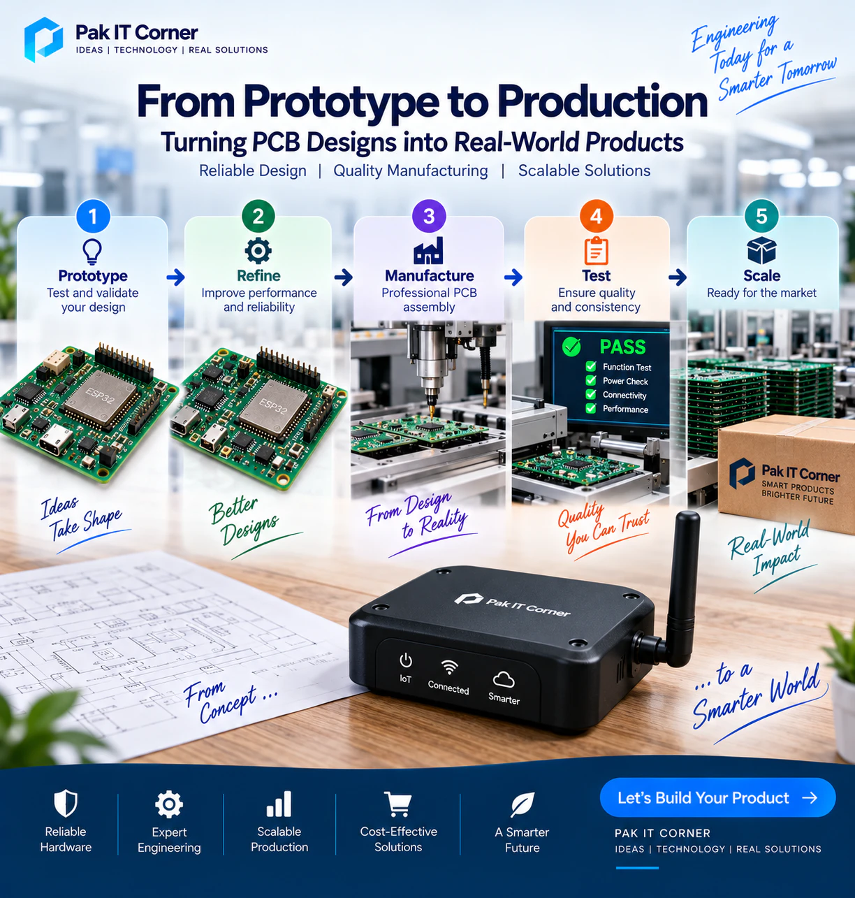
- Start with Proof-of-Concept (POC) Dev Boards: Validate your core software and sensor logic on off-the-shelf ESP32 or STM32 development boards before designing custom silicon layout. Discover our roadmap in ESP32 IoT product development from prototype to production.
- Use Pre-Certified RF Modules: Designing a custom chip-down antenna requires specialized RF lab equipment and thousands of dollars in intentional-radiator FCC/CE certification. Using modular certifications saves 60% to 80% on lab fees.
- Standardize Passive Components: Limiting the variety of resistor and capacitor values on your BOM reduces machine setup fees during assembly.
- Ensure Co-Design of App and Hardware: Building the electronics without consulting the mobile app team often leads to missing status LEDs, neglected pairing buttons, or incompatible Bluetooth MTU configurations.
Plan Your PCB Project with Pak IT Corner
At Pak IT Corner, we combine professional PCB engineering with native mobile and cloud application development. We help hardware creators take ideas from initial schematic capture to tested prototypes and production-ready manufacturing packages.
Whether you need a fresh hardware design, a DFM review on an existing board, or a companion mobile app to control your product, explore our portfolio, review our transparent packages, or contact us today for a scoped technical consultation.
Ready to Build Your Custom Hardware?
Send us your project requirements, block diagrams, or target component list for a realistic, scoped engineering estimate.
Discuss Your PCB Project